Electronics Projects by Htet
Sine wave inverter
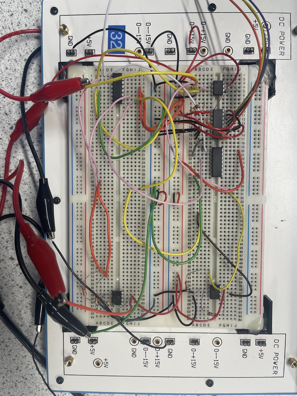
Although the oscillator is implemented using the Wien bridge by calculating and considering the component values to achieve the desired 100Hz frequency, the unsolvable error occurs when feeding the sine wave into zero costing to convert it into a square wave. The following simulations and circuit- building stages are also tested using the signal generator. Interestingly, the zero crossing generates the square wave from the absence of the feedback routing in the circuit. Although the simulation uses two separate counters, the physical circuit combines two counters, and the first counter with the least pulse width is used to drive the second counter to generate 2, 4, and 8 pulses. Noticeably, those generated square pulses are input into the mechanical switch to control the output flow setting. Next, the generated half-pulse square wave and the not gate inputted of it are used to drive the DG211 IC chip for chopping and producing a normal and inverted sine wave based on the setting of the mechanical switch. In the last stage of the system, the signal is amplified to get an appropriate final output. 18 Finally, the design integration showcased an apparent inversion of the input sine wave, with the period responding appropriately to the mechanical switch settings. Although the generated signal from the Wien bridge is not applicable, the potential remedy involves amplifying it with a 100-gain resistor ratio. The transition from simulation to practical implementation was also considered, with the conversion of the sine wave inversion circuit into a PCB 3D design using TE connectivity for VCC, VSS, and ground with Ultiboard.
 Details
AM-modulation
As for networking terms, this project operates on a physical layer. This labwork is about how the AM works in full am and DSB-SC.
 Details
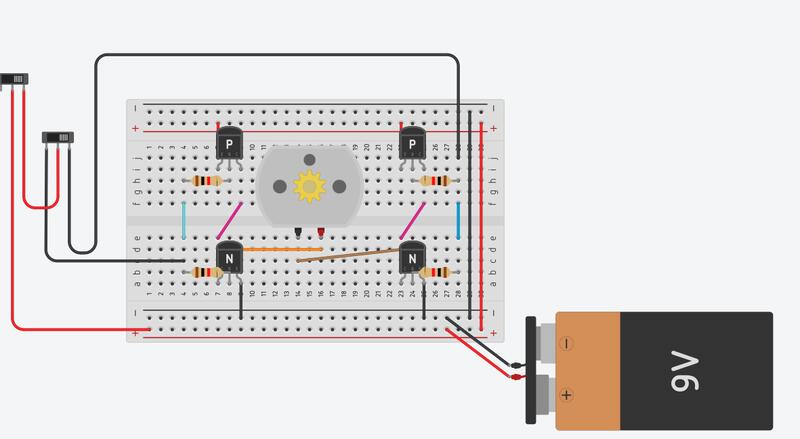
H bridge toy motor design
Simple H bridge toy motor design.
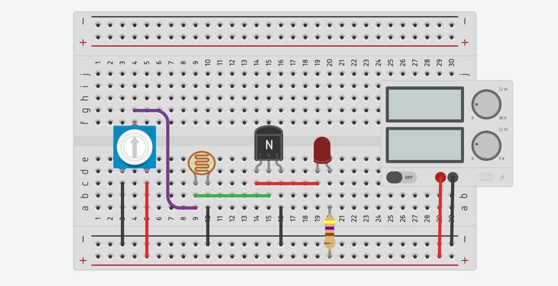
LDR circuit with tinker card
Light dependant resistor circuit
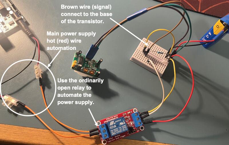
Power saver Circuit with relay transistor and PIR motion sensor.
The LED light control circuit with the PIR motion sensor shown in the link is created. Using a data pin to control the base’s current flow will light up the LED. The measured result indicates the voltage drop between a positive node of the LED and the ground estimate at 8.6V; connecting the relay to those connections will allow the sensor to control a relay. The PIR sensor control relay can achieve by replacing the LED and resistor combination with a relay module (ordinarily close to two red terminals of the main Arduino power supply) as shown below.